
Five practical routes for starting a product selection review.
How to Choose a Blower Wheel for an OEM Project
A blower wheel selection starts with the equipment and system context, not an industry label or a photo. Use this guide to compare routes, collect inputs and decide when to request a project-specific review.
Equipment, duty, geometry, interfaces, environment and validation data.
Identify, compare, clarify and approve the project route.
Final performance remains an equipment-level validation responsibility.
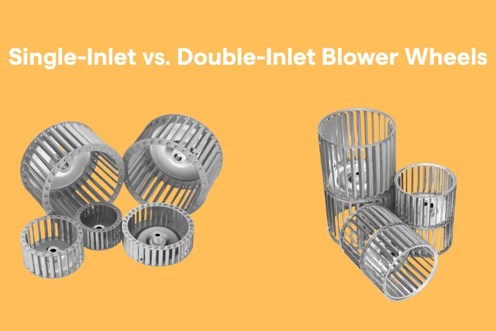
Visual comparison referencesThe images start identification; the project inputs in the guide determine what must be confirmed next.
Start with the difference between a wheel and a fan system
A wheel or impeller is one component. The housing, inlet, outlet, motor, speed, duty and mechanical interfaces influence the final equipment outcome and must be considered together.
Geometry and interface
Wheel type, dimensions, hub or shaft connection, rotation and mounting define the component under review.
Air path and operation
Housing, inlet, outlet, speed, duty and surrounding equipment affect the result in service.
Evidence and validation
The project drawing, requirements and agreed validation method establish what can be approved.
Compare routes by the questions they require
This original planning matrix is a starting point for discussion. It does not assign a universal performance ranking or replace a complete system review.
| Route | Project context to clarify | Key inputs | Review boundary |
|---|---|---|---|
| Forward curved wheel | Equipment air path, inlet arrangement and compact installation context. | Diameter, width, inlet form, hub or shaft, rotation and housing context. | System performance requires the complete equipment conditions. |
| Backward curved wheel | Geometry, duty, speed, mounting and surrounding system constraints. | Wheel geometry, interfaces, operating context and validation needs. | Do not infer efficiency or system outcome from geometry alone. |
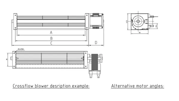
| Cross-flow wheel | Long wheel, air-channel and shaft-end arrangement. | Overall and active length, diameter, both shaft ends, rotation and air channel. | Air distribution depends on the assembly and operating conditions. |
| Oven fan impeller | Equipment environment, interface, rotation and sample or drawing evidence. | Mounting, offset, temperature profile, cleaning context and documentation needs. | Material and operating claims require project-specific evidence. |
Collect the eight inputs that change the decision
Unknown fields can be identified and discussed; critical values should not be guessed.
Equipment and air path
Describe the equipment task, housing, inlet, outlet and any existing component.
Duty and speed context
Record the required operating context and control information available to the project team.
Space and interfaces
Document the available envelope, hub or shaft, mounting, rotation and service access.
Environment and quality
Record the exposure, required documents, inspection scope and proposed validation needs.
Missing information
Clearly mark unknown inputs so a review can identify the next measurement or confirmation task.
Project review
Use the collected inputs to decide the relevant product route and responsible approval step.
Follow a practical selection sequence
The goal is not a quick generic answer. The goal is a sufficiently complete input package for an engineering and manufacturing review.
- 01
Define the equipment task
Start with what the equipment must do and the air path it uses.
- 02
Record existing evidence
Gather the drawing, sample, photos, part markings and known dimensions.
- 03
Identify candidate routes
Compare geometry only after the system and interface context are visible.
- 04
Confirm interfaces and environment
Review the mounting, rotation, space, service access and operating conditions.
- 05
Agree validation and approval needs
Define the project-specific requirements that must be confirmed before production.
Correct the assumptions that cause mismatch
| Assumption | Why it creates risk | Better next step |
|---|---|---|
| Same diameter means a replacement fits. | Width, geometry, hub, shaft ends, offset, rotation and clearance may still differ. | Review the complete interface and equipment context. |
| Same industry means the same wheel type. | Equipment in one industry can use different air paths, duty points and space constraints. | Start with the actual equipment and operating inputs. |
| A photo proves performance. | A photo can help identify geometry but cannot establish the complete system result. | Agree the data and validation method needed for the project. |
| A material name proves environmental suitability. | Exposure, finish, operating conditions and evidence requirements may vary by project. | Describe the environment and documentation requirement for review. |
Choose the next information route
Review wheel types
Use a product page when the geometry is already understood and the interface needs detail.
Browse products →Review equipment context
Use an application page when the equipment need is clearer than the wheel terminology.
Browse applications →Prepare a project review
Use the custom route when you have a drawing, sample or defined engineering question.
Start custom development →This guide organizes inputs; it does not approve a system.
TSLBlower can review manufacturing-related geometry, interfaces and project requirements. The complete equipment system, performance target and validation responsibility should be defined with the responsible project team.
Request a QuoteBlower wheel selection questions
How do I choose a blower wheel type?
Start with the equipment and air path, required flow and pressure, speed, available space, housing and inlet, shaft or mounting interfaces, environment and validation needs. Compare candidate geometries only after these inputs are understood.
What is the difference between forward and backward curved wheels?
The blade outlet direction differs relative to rotation, and the wheels are used in different system designs. Neither should be selected from geometry alone; duty, speed, housing, space, noise target and interfaces must be reviewed.
When should I consider a cross-flow wheel?
A cross-flow route may be discussed when the equipment uses a long cylindrical wheel and housing to distribute air across a width. Length, diameter, both shaft ends, air channel, speed and space must be confirmed.
Can I select a replacement by diameter alone?
No. Width, blade geometry, hub or shaft ends, mounting, offset, rotation, material, balance, housing clearances and equipment conditions can all cause mismatch even when the diameter is the same.
What if some operating data is unknown?
Provide the drawing, sample photos, equipment context and all known values, and mark unknown fields. The review can identify missing information, but no one should guess critical inputs or promise performance without an agreed validation method.
Ready to turn your project information into a quote?
Send the drawing, sample photos, quantity or operating requirements available to your team.